By Ogumex Editorial Team
Designing a large solar array for a manufacturing plant is an industrial power-system project, not simply a panel-count exercise. The design must fit the plant’s operating profile, physical site, electrical infrastructure, utility requirements, safety program and long-term maintenance strategy.
A large roof or open parcel may establish the theoretical maximum capacity, but it does not establish the right capacity. A defensible design begins with measured load data and progresses through site validation, structural and electrical engineering, interconnection studies, protection design, commissioning and lifecycle planning.
This guide outlines the major technical decisions. Project-specific drawings, calculations and settings should be prepared and reviewed by appropriately licensed engineers, qualified contractors, the serving utility and the authorities having jurisdiction.
Establish the plant’s design basis before sizing the array
The first deliverable should be a documented design basis describing what the project is expected to accomplish. Possible objectives include reducing purchased energy, controlling peak demand, supporting critical loads, meeting emissions targets, preparing for plant electrification or improving cost predictability.
These objectives are not interchangeable. A system optimized for annual energy production may differ substantially from one designed to limit exports, reduce a short demand peak or operate a critical process during an outage.
Build an interval load profile
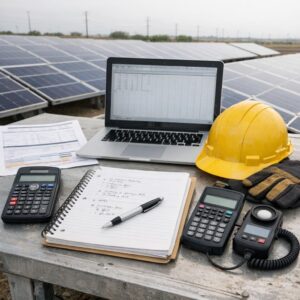
Obtain at least one complete year of interval meter data and, where plant operations vary substantially, consider using 12 to 24 months. Fifteen-minute data are generally preferable when billing demand is measured over short intervals. Hourly data may be adequate for preliminary energy analysis but can hide brief production peaks.
Reconcile the interval data with utility bills and document:
- Monthly and seasonal energy consumption.
- Maximum demand and the utility’s demand-measurement interval.
- Time-of-use periods, demand ratchets, standby charges and export compensation.
- Power-factor or reactive-energy provisions.
- Weekday, weekend, holiday and planned-shutdown behavior.
- Production lines, chillers, compressors, furnaces, refrigeration, dust collection and other major loads.
- Planned expansions, electrified process heat, fleet charging or equipment retirements.
Actual interval data should be used whenever available. Representative profiles can support early screening, but they may not reproduce batch production, shift changes, motor starts or seasonal process loads accurately.
Separate normal, flexible and critical loads
For resilience or microgrid planning, classify loads rather than applying a single percentage to the whole facility:
| Load category | Questions to resolve |
|---|---|
| Continuous process loads | Can the process tolerate interruption, reduced output or a controlled shutdown? |
| Critical safety loads | Which controls, ventilation systems, pumps, alarms and egress systems must remain available? |
| Restart loads | What inrush current, sequencing and auxiliary equipment are required to restart production? |
| Flexible loads | Can charging, pumping, chilling, compressed-air production or other work move into solar hours? |
| Noncritical loads | Which loads can be shed automatically during an outage or demand event? |
The critical-load profile should include both power and energy requirements. It should also identify motor-starting behavior, acceptable outage duration, power-quality tolerances and the consequences of an unsuccessful transition to island operation.
Validate the roof, ground and parking areas
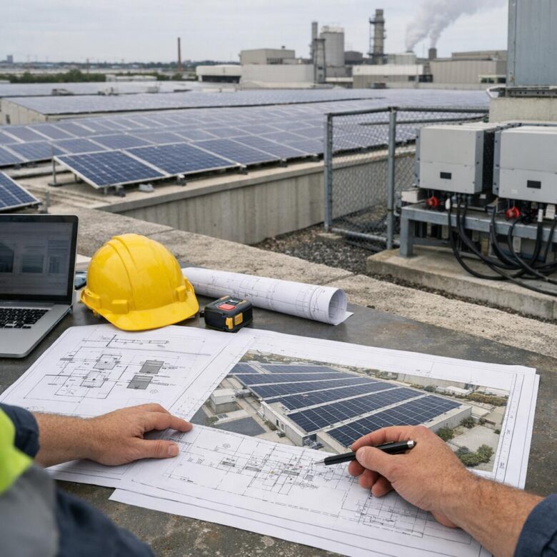
Available area and usable area are rarely the same. Site screening should identify physical, operational, environmental and permitting constraints before the layout is treated as a firm design.
Rooftop arrays
A licensed structural engineer should evaluate the existing structure, available records and site conditions. The analysis may need to address added dead load, construction loading, wind uplift, snow and snow drift, seismic effects, load paths, attachment forces and the condition of the deck and supporting members.
Roof screening should also consider:
- Roof age, remaining service life and replacement schedule.
- Membrane warranty requirements and approved attachment or ballast methods.
- Drains, scuppers and paths needed to inspect and maintain drainage.
- Skylights, smoke vents, roof hatches and fall hazards.
- HVAC equipment, exhausts, cooling towers and future mechanical replacements.
- Fire-service access, pathways and applicable setbacks.
- Corrosive emissions, combustible deposits and hazardous classified locations.
- Safe routes for installation, inspection, cleaning and module replacement.
If the roof is likely to require replacement well before the solar equipment, reroofing first or selecting another array location may be less disruptive than removing and reinstalling the system later.
Ground-mounted arrays
Ground-mounted systems require more than a solar-resource review. Confirm property control, zoning, easements, setbacks, environmental restrictions, underground utilities, geotechnical conditions, flood exposure, grading, erosion control, stormwater management and emergency access.
The layout must coexist with truck circulation, rail spurs, employee access, fire lanes, material storage and future plant expansion. Foundation selection should follow site-specific geotechnical and structural analysis rather than a generic pile or ballast assumption.
Solar carports
Carports can create useful generation area but introduce vehicle clearances, collision exposure, foundations, drainage, lighting, accessible-route and fire-department considerations. Industrial sites should verify clearance for delivery vehicles, lifting equipment and emergency apparatus where relevant. Protective barriers may be needed around columns and electrical equipment.
Weather and environmental exposure
Assess site-specific wind, hail, snow, flooding, wildfire, lightning, salt, dust, chemicals and temperature extremes. Equipment ratings, foundations, enclosures, wire management, drainage and maintenance procedures should respond to the identified hazards. A design based only on average weather can overlook the events most likely to cause extended downtime.
Size the system around operational and interconnection constraints
Model solar generation against the time-series plant load, the applicable tariff and expected export rules. Annual kilowatt-hour matching alone does not show whether the plant can consume the output when it is produced or whether solar will reduce the billing peak.
Evaluate multiple capacities and operating cases, including:
- Maximum onsite consumption with little or no export.
- Permitted export under the utility’s tariff and interconnection agreement.
- Export-limited operation using a certified control scheme.
- Weekend and holiday curtailment.
- Future load growth or reduced production.
- Solar paired with load shifting or battery storage.
- Loss of a major production line or extended plant shutdown.
Modeling should disclose assumptions for solar resource, shading, soiling, module temperature, mismatch, wiring losses, transformer losses, inverter efficiency, clipping, degradation, curtailment and equipment availability. Sensitivity analysis is more useful than presenting a single production estimate as certain.
Choose the DC-to-AC relationship deliberately
A higher DC array capacity relative to inverter AC capacity can improve inverter utilization but may increase clipping during high-production periods. There is no universal optimum. The decision should reflect the local solar resource, array orientation, module behavior, tariff, export limit, equipment cost and expected operating temperatures.
For facilities with several roofs or orientations, the model should account for the combined output profile rather than assuming all subarrays reach maximum output simultaneously.
Develop a layout that supports production and maintenance
Detailed shading analysis should include parapets, rooftop equipment, vents, silos, stacks, cranes, utility poles, nearby structures and planned additions. Exhaust plumes and deposits can create localized soiling or corrosion even where shading is limited.
Module tables, inverters, combiner equipment and transformers should be arranged to provide:
- Required working clearances and emergency access.
- Practical cable routes with protection from abrasion, heat, water and mechanical damage.
- Access for testing, thermal inspection and equipment replacement.
- Drainage paths that are not obstructed by foundations, ballast or conduits.
- Separation from process vents and hazardous locations where required.
- Crane or lifting access for major component replacement.
- Secure but usable disconnect and shutdown locations.
Connector compatibility, conductor support and wire management deserve explicit specifications and inspection points. Improvised field connections, unsupported conductors and plastic ties not suited to the environment can become recurring failure sources.
Verify the plant’s electrical infrastructure
Existing electrical equipment can impose a lower project limit than the available solar area. Review original drawings, utility records and field conditions rather than relying solely on an outdated one-line diagram.
The electrical assessment should document:
- Service voltage, utility transformer and point of common coupling.
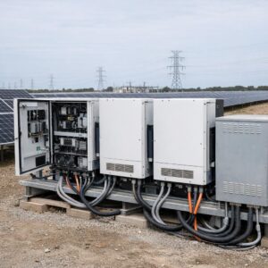
- Main switchgear, switchboards, panelboards, bus ratings and available connection points.
- Equipment interrupting and short-circuit current ratings.
- Existing generators, uninterruptible power supplies, capacitors and power-factor correction equipment.
- Grounding and bonding configuration.
- Available space, working clearances and equipment condition.
- Feeder routes, conductor capacity and voltage-drop constraints.
- Metering, supervisory control and plant energy-management interfaces.
Complete the necessary electrical studies
The scope depends on system size, voltage and facility complexity, but may include:
- Load-flow and voltage analysis.
- Short-circuit and equipment-duty analysis.
- Protective-device coordination.
- Arc-flash assessment and labeling updates.
- Grounding and bonding analysis.
- Harmonic and power-quality studies.
- Reactive-power and voltage-control analysis.
- Motor-starting or process-restart studies for microgrids.
- Transient, islanding or stability studies where warranted.
Adding inverter-based generation changes fault-current paths and operating conditions. Existing breakers, relays and settings should not be assumed to remain adequate without analysis.
Start interconnection work during concept design
Utility interconnection is frequently a critical schedule and cost constraint. Contact the serving utility before freezing system capacity, the point of interconnection or major equipment selections.
Confirm the utility’s application process, required studies, metering arrangement, communications, equipment certifications, protection functions, export limits, witness testing and upgrade responsibilities. Distribution-system capacity and utility construction schedules can change the feasible project size or commercial case.
Interconnection requirements may reference the IEEE 1547 family of standards, but the controlling requirements are the utility rules, approved settings, interconnection agreement, locally adopted codes and authority approvals applicable to the specific project.
Coordinate protection as a complete system
Protection design may include anti-islanding functions, voltage and frequency response, ground-fault protection, overcurrent protection, reverse-power functions, transfer-trip schemes, visible isolation, relays and communications. Settings should be coordinated among the utility, inverters, plant switchgear, generators, transfer equipment and microgrid controller.
If export limiting is used, document the measurement architecture, control response, loss-of-communications behavior, failure mode, backup protection and commissioning test. An export-control concept is not complete until the utility accepts it and its field performance has been demonstrated.
Add battery storage only for a defined use case
Battery storage should solve a quantified operational or tariff problem. Common use cases include reducing demand peaks, shifting solar output, complying with an export limit, supporting critical loads or improving microgrid operation.
Power and energy ratings must be evaluated separately. A battery with sufficient energy for several hours may still lack the power or overload capability needed to start large motors. Conversely, a high-power battery may be too small to sustain loads through a long outage.
Storage analysis should address:
- Usable energy at the required operating conditions.
- Charge and discharge power.
- State-of-charge reserve and dispatch priorities.
- Round-trip losses, degradation and augmentation strategy.
- Thermal management and auxiliary loads.
- Warranty operating limits.
- Fire detection, ventilation, separation and emergency response.
- Controls, communications and cybersecurity.
- Decommissioning and end-of-service responsibilities.
For stationary storage, the design team and authority having jurisdiction should identify the applicable edition of NFPA 855, adopted electrical and fire codes, and required product certifications. UL 9540 addresses energy storage systems and equipment, while UL 9540A is a test method used to evaluate thermal-runaway fire propagation. A UL 9540A report should not be described as a general product certification.
Treat backup power and microgrid operation as a separate design mode
Grid-connected solar normally shuts down when the utility source is unavailable unless the facility has equipment and controls specifically designed for intentional island operation. Installing solar and a battery does not by itself create a functional microgrid.
A microgrid design should define:
- The electrical boundary of the island.
- Grid-forming and grid-following equipment roles.
- Black-start and restart sequences.
- Automatic and manual load-shedding priorities.
- Generator synchronization and minimum-loading limits.
- Protection behavior in grid-connected and islanded modes.
- Transition time and whether sensitive processes can tolerate it.
- Fuel availability and generator runtime assumptions.
- Operator authority, alarm handling and recovery procedures.
Test the microgrid against credible seasonal outages, including low-solar periods and outages that begin at an unfavorable battery state of charge. A single idealized outage scenario is not sufficient for a critical industrial process.
Integrate safety into engineering and construction planning
Photovoltaic conductors can remain energized in daylight after the AC system or utility connection has been opened. Designs and work procedures must account for multiple energy sources, stored energy, backfeed and the limitations of each disconnecting method.
Project safety planning should address:
- Electrical shock, arc-flash and arc-blast hazards.
- Lockout/tagout and verification of isolation.
- Rooftop edges, skylights, hatches, ladders and scaffolds.
- Crane lifts, rigging and material handling.
- Heat, weather and site-specific industrial hazards.
- Restricted and hazardous classified areas.
- Emergency shutdown, responder access and durable labeling.
- Changes to plant emergency, switching and maintenance procedures.
OSHA distinguishes between requirements applying to construction work and those applying to general-industry maintenance. The employer, constructor and facility owner should assign responsibilities clearly and ensure that electrical work is performed by qualified personnel under an appropriate electrical safety program.
Specify engineering and quality requirements before procurement
Procurement documents should define more than equipment nameplates and an annual energy target. Include the design criteria, applicable codes and standards, utility requirements, environmental ratings, required studies, documentation, quality-control hold points, commissioning procedures and O&M deliverables.
Useful required submittals include:
- Stamped civil, structural and electrical drawings as applicable.
- Structural calculations and geotechnical recommendations.
- Updated one-line and three-line diagrams.
- Short-circuit, coordination and arc-flash reports.
- Protection philosophy, relay settings and utility approvals.
- Equipment data sheets, certifications and environmental ratings.
- Energy model assumptions and loss diagram.
- Factory and field quality-control plans.
- Cybersecurity and communications architecture.
- Commissioning, training, O&M and decommissioning plans.
Performance guarantees should state the reference weather data, measurement method, availability exclusions, curtailment treatment and responsibility for meter and sensor accuracy. Otherwise, actual and modeled output may not be comparable.
Commission the entire integrated power system
Develop and budget the commissioning plan before construction begins. Commissioning should verify the approved design, installation quality, safety functions, control logic, protection settings, metering and performance—not merely confirm that the inverters turn on.
The project-specific plan may include:
- Document and drawing review.
- Equipment receipt and installation inspections.
- Fastener and connection verification according to approved procedures.
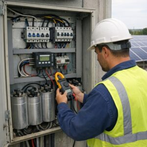
- Polarity, continuity and insulation-resistance testing.
- String or array testing where applicable.
- Grounding and bonding verification.
- Protective-relay and trip testing.
- Inverter setting and communications verification.
- Meter, sensor, weather-station and data-validation checks.
- Export-limit and fail-safe testing.
- Emergency-stop and shutdown demonstrations.
- Microgrid transition, black-start and load-shedding tests where applicable.
- Whole-system performance testing and resolution of punch-list items.
Testing should be witnessed by the appropriate owner, engineer, utility or authority representatives. The owner should receive a baseline commissioning report and an organized record of final settings and test results.
Design the O&M program with the plant
Operations and maintenance should influence the layout and contract from the beginning. Systems that cannot be accessed, isolated, monitored or repaired safely will be expensive to maintain regardless of initial equipment quality.
The O&M plan should define:
- System ownership, operator roles and emergency contacts.
- Alarm priorities, response times and escalation procedures.
- Weather-corrected performance and availability monitoring.
- Preventive inspection and electrical testing intervals.
- Condition-based cleaning and vegetation management.
- Roof, drainage, corrosion and wire-management inspections.
- Thermal inspections and fault investigation procedures.
- Spare-parts strategy and replacement lead times.
- Firmware, software, password and configuration management.
- Severe-weather preparation and post-event inspection.
- Warranty claim, insurance and incident-documentation processes.
Do not repeatedly reset a tripped inverter without investigating the cause. Ground faults, insulation damage, water entry or failing components can remain concealed after a reset. Corrective work should follow the manufacturer’s instructions, the facility’s hazardous-energy procedures and qualified-person requirements.
Require a complete handover package
Before final acceptance, obtain as-built drawings, final settings, approved studies, equipment manuals, test reports, warranties, product certifications, spare-parts lists, training records, utility approvals, inspection records and software credentials. The plant should control or have durable access to monitoring data and configuration files.
Common mistakes to avoid
- Sizing from available area alone: This can create uneconomic exports, curtailment or utility upgrades.
- Using annual consumption without interval data: Annual totals do not reveal peak-demand timing or shutdown periods.
- Assuming solar will provide backup power: Intentional island operation requires dedicated equipment, controls and protection.
- Ignoring existing equipment condition: Aging switchgear, transformers or roofs can change the project scope materially.
- Deferring interconnection: Utility studies and required upgrades can alter capacity, cost and schedule.
- Adding storage without dispatch analysis: Battery value depends on the tariff, load shape, operating limits and use case.
- Under-scoping protection studies: New generation affects fault paths, coordination and operating modes.
- Treating commissioning as startup: Energization alone does not prove protection, controls, metering or performance.
- Leaving O&M until handover: Access, monitoring and spare-parts requirements must be designed and procured earlier.
A practical industrial solar design sequence
- Define energy, demand, resilience and emissions objectives.
- Collect interval load, tariff, production and expansion data.
- Screen roof, land and parking areas for fatal constraints.
- Engage the utility and authority having jurisdiction.
- Model several solar, storage and export cases.
- Complete structural, civil and electrical due diligence.
- Develop the interconnection and protection concept.
- Issue performance-based technical specifications and reviewed drawings.
- Execute construction quality control and integrated commissioning.
- Accept the system only after documentation, training and O&M readiness are complete.
Closing recommendations
The strongest industrial solar designs begin with measured plant behavior and finish with a maintainable, documented power system. Roof area and module efficiency matter, but they do not replace structural verification, electrical studies, utility coordination, protection engineering, safety planning or commissioning.
Before procurement, require review by licensed engineers with experience relevant to the project’s structural system, voltage level, protection scheme and operating modes. Storage and microgrid projects may also require specialized fire-protection, controls, communications and process-safety expertise.
A successful array is not simply one that produces substantial energy. It is one that can be interconnected, operated, isolated, inspected and maintained without compromising the manufacturing plant or the people who work there.
Sources and further reading
- U.S. Department of Energy: Procure a New Photovoltaic System
- NREL: REopt Load Profile Input Guidance
- IEEE Standards Association: IEEE 1547-2018
- U.S. Department of Energy: Install and Commission a Photovoltaic System
- U.S. Department of Energy: Operate and Maintain an Existing Photovoltaic System
- OSHA: Solar Energy Electrical Hazards
- OSHA: Solar Energy Fall Hazards
- OSHA: Solar Energy Lockout/Tagout
- NFPA 70: National Electrical Code, 2026 Edition
- NFPA 855: Standard for the Installation of Stationary Energy Storage Systems, 2026 Edition
- UL Solutions: Energy Storage System Testing and Certification

The Ogumex Editorial Team creates practical, research-based content about commercial solar energy, battery storage, clean technologies, and sustainable industrial solutions. Our goal is to explain complex topics clearly, helping professionals, businesses, and informed readers make better decisions. Each article is reviewed for clarity, accuracy, and usefulness using reliable industry and official sources.