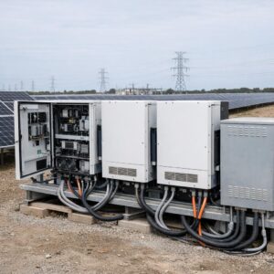

A solar installation can reduce the active power imported by an industrial facility without removing the reactive demand created by motors, transformers, compressors, pumps, HVAC equipment, and other loads. The result may be a worse power factor at the utility meter even though the photovoltaic system is producing normally.
Electrical safety warning: industrial photovoltaic systems, capacitor banks, switchgear, transformers, generators, batteries, and medium-voltage equipment can retain dangerous energy and present shock, arc-flash, fire, and equipment-damage risks. Do not open cabinets, connect test instruments, change protection settings, modify inverter grid functions, or install correction equipment unless you are qualified, authorized, and following the applicable safety procedures.
Power factor problems after a solar project is commissioned are often misunderstood. The panels may be producing the expected kilowatts, the inverters may show no internal fault, and total grid electricity consumption may be falling. At the same time, the utility bill may show a power factor penalty, a leading-reactive condition, or an unexpected increase in reactive demand relative to net active import.
The correct response is not to immediately add a larger capacitor bank. The facility must first determine whether the problem involves lagging reactive demand, excessive capacitive correction, harmonic distortion, voltage-control interaction, inverter settings, current-transformer placement, or the way the utility calculates the billing value.
Key principle: measure the power factor at the same point and during the same intervals used by the utility. A correction that improves one internal panel may not fix the reading at the point of common coupling or billing meter.
Understanding Active, Reactive, and Apparent Power
Industrial AC systems are commonly described using three related power quantities. Understanding their relationship helps explain why power factor can fall after on-site solar reduces grid-imported active power.
In a simplified sinusoidal system, apparent power can be represented as the square root of kW² plus kVAR². Harmonic-rich and unbalanced systems require more complete measurement methods.
A power factor close to 1.0 indicates that active power represents most of the apparent power. A lower value means more current may be required to deliver the same amount of useful active power, depending on the voltage, phase configuration, distortion, and operating conditions.
Displacement power factor and true power factor are not always identical. Displacement power factor describes the phase relationship of the fundamental-frequency voltage and current. True power factor also reflects waveform distortion. A capacitor bank may improve displacement power factor without solving harmonic distortion.
Why Solar Can Make the Metered Power Factor Look Worse
Photovoltaic inverters primarily supply active power unless they are configured and permitted to provide or absorb reactive power. When solar output rises, the facility imports fewer kilowatts from the grid. However, industrial motors, transformers, and other inductive loads may continue drawing reactive power.
The load inside the facility may not have changed, but the ratio measured at the utility meter can change significantly.
The utility supplies most of the facility’s active and reactive power.
Solar supplies 500 kW locally, while the grid continues supplying approximately 300 kVAR.
This simplified example shows why the billing power factor can fall at midday. The solar system reduced grid-imported active power, but it did not automatically remove the facility’s reactive requirement.
This does not necessarily mean the photovoltaic system is defective. It may indicate that the facility’s previous correction strategy was designed for a load profile that no longer exists after on-site generation was added.
Recognize the Main Symptoms
| Observed Symptom | Possible Explanation | First Information to Review |
|---|---|---|
| Power factor falls during sunny hours | Grid-imported kW falls while plant reactive demand remains | Time-aligned utility, load, inverter, kW, kVAR, and kVA data |
| Power factor becomes leading at low load | Too many capacitor stages remain connected | Capacitor-controller settings, switching history, and minimum-load periods |
| Capacitors overheat or fuses operate | Harmonic stress, resonance, failed components, or incorrect rating | Harmonic survey, capacitor current, temperature, ventilation, and inspection |
| Inverters trip or curtail | Voltage rise, grid-setting conflict, protection event, or control interaction | Inverter logs, voltage trends, grid settings, and interconnection requirements |
| Internal readings improve but penalties remain | Correction point or interval does not match utility billing measurement | Tariff, billing-meter interval, point of common coupling, and CT locations |
| Frequent capacitor switching | Controller hunting, rapidly changing load, solar variation, or small stage sizes | Switching log, controller delay, stage sequence, and operating profile |
Measure the Site Before Selecting Equipment
One spot reading is rarely enough. Solar production, industrial loading, process schedules, HVAC demand, generator operation, and capacitor switching can change throughout the day.
A qualified power-quality professional should collect synchronized interval data at the relevant points. Useful operating periods include early morning, midday, late afternoon, nighttime, weekends, low production, peak production, generator operation, battery charging, and battery discharging where applicable.
Questions the Survey Should Answer
- Does the problem occur only when solar production is high?
- Is the site lagging, leading, distorted, or moving between conditions?
- What does the utility measure and during which billing interval?
- Which loads contribute most of the reactive demand?
- Are capacitor stages switching correctly?
- Are current transformers installed with the correct location and polarity?
- Do inverter logs show voltage or reactive-power commands?
- Are harmonics significant before capacitors are connected?
- Does generator operation require a different correction strategy?
- Does battery charging or discharging change the meter behavior?
Do not size a capacitor bank from a monthly penalty alone. A monthly bill may not reveal whether the problem occurs for a few intervals, whether the condition is leading or lagging, or whether harmonics make ordinary capacitors unsuitable.
Follow a Structured Correction Process
-
Review the utility tariff and interconnection agreement.
Confirm the required power factor range, whether leading and lagging values are treated differently, the billing interval, the measurement point, and any requirements for inverter reactive-power operation. -
Collect synchronized operating data.
Compare utility interval data, facility load, solar production, inverter status, capacitor stages, generators, batteries, and major process loads using matching timestamps. -
Perform a power-quality survey.
Measure voltage, current, kW, kVAR, kVA, true power factor, displacement power factor, imbalance, and harmonic distortion at the appropriate points. -
Inspect existing correction equipment.
Review capacitor condition, reactors, fuses, contactors, ventilation, controller programming, current-transformer placement, stage size, switching delay, and maintenance history. -
Review inverter capabilities and approved settings.
Check the exact inverter model, firmware, capability curve, commissioning records, utility approval, and permitted grid-support functions. -
Model several operating conditions.
Evaluate no solar, partial solar, maximum solar, minimum facility load, peak load, generator operation, and battery operating modes where relevant. -
Select a coordinated correction method.
Choose inverter support, automatic capacitors, detuned banks, harmonic filters, load-side correction, transformer changes, or a combined solution based on measured behavior. -
Commission under real conditions.
Verify voltage, current, power factor, harmonics, inverter output, capacitor switching, alarms, and protection behavior across representative load and solar levels. -
Monitor subsequent billing cycles.
Confirm that the utility measurement improved and that the correction did not introduce leading power factor, excessive switching, voltage problems, overheating, or inverter events.
Correction Methods and Their Best Uses
Automatic Capacitor Bank
The controller switches capacitor stages as reactive demand changes. This can suit facilities with lagging inductive loads and acceptable harmonic conditions.
Main caution: stages that remain connected during light-load or high-solar periods can create leading power factor or voltage rise.
Detuned Capacitor Bank
Reactors are combined with capacitors to change the system response and reduce the risk of harmful resonance under the intended design conditions.
Main caution: the design must be based on system and harmonic measurements, not a generic detuning choice.
Active Harmonic Filter
Active filters can respond to changing harmonic currents and may also provide reactive compensation, depending on their rating and configuration.
Main caution: verify current capacity, measurement location, response requirements, coordination, and operating limits.
Inverter Reactive-Power Control
Approved inverters may support fixed power factor, fixed reactive power, volt-var, or other utility-directed functions.
Main caution: reactive operation uses inverter current capacity and must be coordinated with voltage, active-power output, protection, and interconnection requirements.
| Method | Often Appropriate When | Important Limitation |
|---|---|---|
| Central automatic capacitor bank | Facility has variable lagging reactive demand | May overcorrect at low net import and may require harmonic detuning |
| Correction near large motors | A few inductive loads dominate reactive demand | Requires correct switching so capacitors do not remain connected improperly |
| Detuned capacitor bank | Measured harmonic conditions make plain capacitors risky | Requires a study of system impedance and harmonic spectrum |
| Active harmonic filter | Nonlinear loads and distortion change dynamically | Higher complexity and cost than basic compensation |
| Solar inverter support | Utility-approved functions can support PF or voltage objectives | Available kVAR may change with active output and inverter rating |
| Load scheduling or energy management | Process loads can be aligned with solar production | Does not replace correction when reactive demand remains excessive |
Use Inverter Settings Carefully
Modern grid-connected inverters may include several voltage and reactive-power functions. Their availability depends on the exact product, firmware, certification, local rules, utility settings, and commissioning configuration.
| Control Mode | Possible Purpose | Main Caution |
|---|---|---|
| Fixed power factor | Maintain an approved leading or lagging target | May not adapt to rapidly changing plant load |
| Fixed reactive power | Provide or absorb a defined amount of kVAR | Can overcorrect when load or solar output changes |
| Volt-var | Adjust reactive power in response to voltage | Must match the approved curve and feeder conditions |
| Power factor versus active power | Change reactive behavior with inverter output | Requires careful configuration and commissioning |
| Volt-watt | Reduce active power when voltage rises | Can reduce energy production and is not a direct PF correction method |
A change that improves the meter reading at one production level may cause a different problem later in the day. Multiple inverters may also respond differently if their firmware, ratings, control priorities, or settings are not consistent.
Treat grid-support settings as controlled engineering parameters. Record the original values, reason for the change, authorization, firmware version, test results, and rollback procedure. Confirm whether utility approval is required before modification.
Harmonics Change the Correction Strategy
Variable-frequency drives, rectifiers, uninterruptible power supplies, welders, soft starters, electronic power supplies, LED drivers, inverters, and other nonlinear equipment can produce nonsinusoidal current.
Capacitors interact with the electrical system impedance. Under unfavorable conditions, an ordinary capacitor bank can amplify specific harmonic currents, increase heating, operate protection devices, damage capacitor elements, or create resonance.
This is why a facility should not assume that low power factor is only a fundamental-frequency phase-angle problem. The power-quality survey should distinguish displacement power factor from true power factor and evaluate the harmonic spectrum at the relevant point.
IEEE 519 evaluates steady-state harmonic conditions at the point of common coupling. Internal equipment limits, manufacturer requirements, and local utility rules may require additional measurements at other locations.
Educational kVAR Correction Calculator
The calculator below estimates the fundamental-frequency capacitor kVAR needed to move from an existing lagging displacement power factor to a higher target.
Screening Estimate for Reactive Compensation
Enter positive active power and power-factor values between 0 and 1. The target must be higher than the existing value.
Do not use this calculator as a purchase specification. It assumes a simplified lagging, sinusoidal condition at one operating point. Industrial solar facilities require interval measurements, minimum-load analysis, harmonic assessment, voltage review, equipment ratings, switching design, and professional verification.
Coordinate the Entire Electrical System
Power factor correction should account for the point of common coupling, main transformer, utility meter, solar inverters, capacitor banks, harmonic filters, voltage regulators, generators, batteries, and large industrial loads.
A generator may have different reactive-power limits from the utility grid and may respond poorly to excessive leading power factor. A battery energy-storage system adds another inverter-based resource that can charge, discharge, import, export, and potentially provide reactive support.
Lightly loaded transformers can continue drawing magnetizing reactive power even when solar reduces active power flowing through the transformer. Current-transformer placement can also cause an automatic capacitor controller to respond incorrectly if it does not measure the intended combination of grid, load, and solar current.
Large sites often benefit from a coordinated power-system study. The study may include load flow, voltage rise, capacitor sizing, harmonics, resonance, transformer loading, inverter capability, protection coordination, and generator or battery operating modes.
Common Mistakes That Make the Problem Worse
| Mistake | Possible Consequence | Better Approach |
|---|---|---|
| Adding capacitors from a single meter reading | Leading power factor or overvoltage during light load | Use interval measurements across representative operating conditions |
| Ignoring harmonics | Overheating, fuse operation, resonance, and premature capacitor failure | Complete a harmonic survey before selecting correction equipment |
| Changing inverter settings without approval | Interconnection noncompliance, curtailment, trips, or unstable voltage | Review utility requirements and document approved commissioning changes |
| Correcting the wrong location | Internal current improves while utility penalty remains | Confirm the billing point and objective of centralized or local correction |
| Ignoring weekends and minimum load | Capacitive overcorrection when solar output remains high | Test the lowest expected net-import condition |
| Allowing capacitor and inverter controls to work against each other | Repeated switching, voltage variation, and unnecessary reactive circulation | Coordinate control targets, time delays, priorities, and measurement points |
| Using one operating mode for grid and generator supply | Generator instability or unacceptable leading power factor | Create and test suitable operating modes for each source condition |
Commissioning Checklist
- Confirm the approved power-factor target and measurement point
- Record original inverter and capacitor-controller settings
- Verify current-transformer location, ratio, orientation, and polarity
- Inspect capacitor stages, reactors, fuses, contactors, and ventilation
- Test minimum load with high solar output
- Test normal and peak production conditions
- Check generator and battery operating modes where applicable
- Measure voltage and current imbalance
- Measure harmonic conditions with correction connected
- Review inverter alarms and curtailment events
- Confirm stable switching without controller hunting
- Compare results with subsequent utility interval and billing data
When Professional Support Is Essential
Professional assessment is appropriate whenever the facility includes medium-voltage equipment, large transformers, high-capacity inverters, capacitor banks, harmonic distortion, generators, battery storage, repeated utility penalties, unexplained voltage changes, or production processes that cannot tolerate downtime.
Stop trial-and-error adjustments and obtain qualified assistance when capacitors overheat, swell, leak, make unusual noise, repeatedly operate fuses, or switch excessively. Repeated inverter trips, unstable voltage, strong harmonic readings, or leading power factor also indicate that the issue may be more complex than a basic billing correction.
Do not approach or open visibly damaged equipment. Follow the facility’s emergency, isolation, lockout/tagout, arc-flash, and manufacturer procedures. Capacitors can retain stored energy after disconnection.
Final Recommendation
Power factor issues in industrial solar installations should be solved with synchronized measurement, correct interpretation, and coordination between the utility meter, industrial loads, photovoltaic inverters, correction equipment, transformers, generators, and batteries.
Begin by confirming the utility rule and determining whether the site has lagging reactive demand, leading overcompensation, harmonic distortion, voltage interaction, or a measurement problem. Inspect existing equipment before purchasing new hardware, and evaluate the lowest-load as well as the highest-production conditions.
The most reliable solution may combine automatic load-side correction, harmonic mitigation, approved inverter reactive-power support, improved controls, and continuous monitoring. The final design should improve the utility measurement without creating resonance, overvoltage, excessive switching, inverter curtailment, generator instability, or new safety risks.
Frequently Asked Questions
Why did power factor become worse after solar was installed?
Solar may reduce active power imported from the grid while motors, transformers, and other loads continue requiring reactive power. The utility meter then sees a lower kW value relative to kVA or kVAR, which can reduce the calculated power factor.
Can the solar inverter correct the facility power factor?
Some inverters can provide or absorb reactive power, but the available functions, current limits, active-power trade-offs, firmware, utility permission, and interconnection settings must be verified. Inverter control is not a universal replacement for correcting plant loads.
Is a capacitor bank always the correct solution?
No. Capacitors can correct lagging displacement power factor, but they may create leading power factor during light load and can interact with harmonics. Measurement should determine whether ordinary capacitors, detuned equipment, active filtering, inverter support, or another approach is appropriate.
What is the difference between leading and lagging power factor?
Lagging power factor is commonly associated with inductive reactive demand from motors and transformers. Leading power factor is commonly associated with excessive capacitive reactive power. Either condition may create billing or technical concerns depending on the utility and system design.
Why can power factor be worst around midday?
Midday may combine high solar production with continuing industrial reactive demand. Grid-imported active power falls, while reactive power may remain. Existing capacitor stages may also stay connected too long and create leading power factor.
Where should correction equipment be installed?
The correct location depends on the objective. Central correction can influence the utility-meter reading, while local correction may reduce current within part of the facility. Some sites need a coordinated combination. The measurement point, switching method, voltage, harmonics, and operating modes must be considered.
Does battery storage affect the power-factor strategy?
Yes. Battery inverters may charge, discharge, import, export, and provide reactive support. Their controls must be coordinated with solar inverters, capacitor banks, generators, industrial loads, and the site energy-management system.
When is a power-system study recommended?
A study is especially useful when solar capacity is large relative to minimum facility load, medium voltage is involved, harmonics are present, capacitors are failing, inverters trip, or the site includes generators or battery storage.
Official References and Further Reading
- IEEE 1547 — Interconnection and Interoperability of Distributed Energy Resources
- IEEE 1547.2 — Application Guide for IEEE 1547
- IEEE 519-2022 — Harmonic Control in Electric Power Systems
- IEEE 1459 — Definitions for Measurement of Electric Power Quantities
- OSHA 1910.333 — Selection and Use of Electrical Work Practices
- NFPA 70E — Standard for Electrical Safety in the Workplace

The Ogumex Editorial Team creates practical, research-based content about commercial solar energy, battery storage, clean technologies, and sustainable industrial solutions. Our goal is to explain complex topics clearly, helping professionals, businesses, and informed readers make better decisions. Each article is reviewed for clarity, accuracy, and usefulness using reliable industry and official sources.