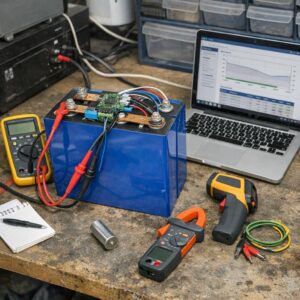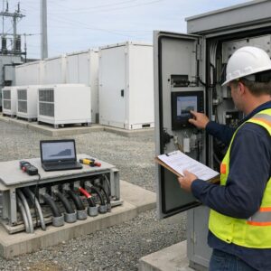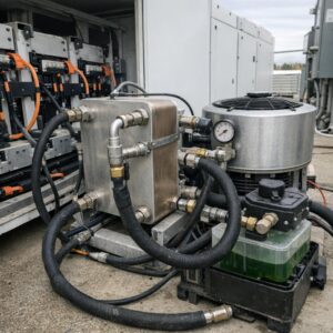
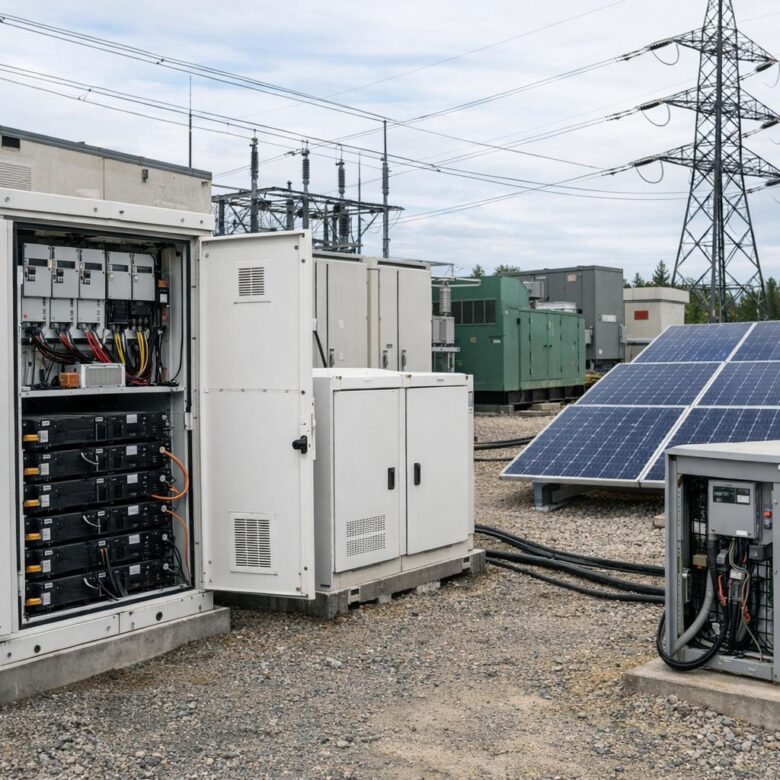
Integrating solar storage with existing industrial microgrids is not just a matter of adding batteries beside solar panels. In an industrial site, storage affects power quality, protection settings, load priorities, backup strategy, operating costs, and the way the microgrid responds during grid-connected and islanded operation.
The main goal is to make solar energy more controllable. Solar production changes during the day, while industrial loads can be demanding, repetitive, sensitive, or sudden. A properly integrated battery energy storage system can absorb excess solar generation, discharge during high-demand periods, support critical loads, and reduce dependence on diesel generators or utility imports.
For existing industrial microgrids, the biggest challenge is compatibility. The site may already have switchgear, generators, transformers, protection relays, SCADA systems, power meters, and a microgrid controller. Solar storage must work with these assets instead of creating conflicts, nuisance trips, reverse power flow issues, or unstable transitions.
A safe integration plan starts with data. Before selecting batteries or inverters, the facility should understand its load profile, critical processes, power quality limits, utility interconnection rules, backup requirements, and operating modes. Without this foundation, even high-quality equipment can perform poorly.
This guide explains the practical steps, technical checks, common mistakes, and decision points involved in adding solar storage to an industrial microgrid. The focus is on clear planning, safe execution, and realistic operation rather than generic claims about energy savings.
Important safety note: industrial microgrid integration involves electrical risk, protection coordination, utility interconnection, battery safety, and operational reliability. Design, installation, testing, and commissioning should be handled by qualified electrical engineers, licensed contractors, and approved equipment vendors according to applicable codes and local regulations.
How Solar Storage Changes an Existing Industrial Microgrid
Solar storage adds flexibility to a microgrid because it separates the moment energy is produced from the moment energy is used. Instead of exporting excess solar power, curtailing PV output, or relying immediately on generators, the battery can store energy and release it when the facility needs it most.
In practice, this can improve peak demand control, backup duration, renewable energy usage, and power stability. For example, a manufacturing plant with high daytime solar output but heavy evening loads may use storage to shift part of that solar energy into later operating hours. A cold storage facility may use batteries to protect refrigeration loads during short utility interruptions.
The battery also changes how the microgrid behaves during disturbances. If the storage inverter can operate in grid-forming mode, it may help establish voltage and frequency during islanded operation. If it is only grid-following, it may need another source, such as a generator or grid-forming inverter, to provide the electrical reference.
| Integration area | Why it matters | What to verify |
|---|---|---|
| Power flow | Solar and storage can change import, export, and internal feeder loading. | Check transformer capacity, feeder limits, reverse power flow rules, and metering configuration. |
| Protection coordination | New inverter-based resources can affect fault behavior and relay settings. | Review short-circuit studies, relay curves, anti-islanding functions, and breaker ratings. |
| Microgrid control | The controller must know when to charge, discharge, curtail, island, or reconnect. | Confirm communication protocols, operating priorities, setpoints, and fail-safe behavior. |
| Critical loads | Batteries should support the most important processes before nonessential loads. | Classify loads by safety, production impact, restart time, and backup duration needed. |
| Battery safety | Industrial storage systems require thermal, fire, ventilation, and emergency planning. | Review enclosure rating, battery management system, fire detection, spacing, and emergency procedures. |
Assess the Existing Microgrid Before Choosing Battery Size
A common mistake is starting with battery capacity before understanding the site. In an industrial microgrid, the correct battery size depends on load behavior, solar production, operating goals, backup requirements, and control strategy. A battery sized only by daily energy use may be too small for peak shaving or too expensive for the real benefit it delivers.
Start with at least 12 months of interval data if available. Fifteen-minute or five-minute data is better than monthly bills because it reveals peaks, ramps, weekend patterns, seasonal changes, and abnormal demand events. If the facility has sensitive machinery, power quality data may also be needed.
During this assessment, separate critical loads from flexible loads. A production line, safety system, refrigeration unit, data server, pump, or compressed air system may have different backup priorities. Some loads can be delayed, while others must stay energized continuously.
- Collect utility bills, interval meter data, generator logs, and solar production records.
- Identify critical, important, flexible, and nonessential loads.
- Review single-line diagrams, switchgear ratings, transformer loading, and feeder layout.
- Check whether the existing microgrid controller supports storage dispatch.
- Confirm utility interconnection limits, export rules, and required protection functions.
- Document outage history, power quality complaints, and production losses caused by interruptions.
- Review available space, ventilation, access routes, fire separation, and maintenance clearance.
Na prática, the best storage projects usually begin with a load and operations study, not with a product quote. This prevents overspending and helps the engineering team select equipment that solves the actual problem.
Define the Operating Goals of the Solar Storage System
Solar storage can serve several purposes, but trying to maximize every use case at once can create conflicting priorities. A battery used mainly for backup may need to remain partially charged. A battery used aggressively for peak shaving may not have enough reserve during an outage. A battery used for solar self-consumption may need a different dispatch schedule than one used for power quality support.
The facility should define its primary, secondary, and optional goals. This decision affects battery capacity, inverter rating, control logic, state-of-charge limits, warranties, and expected cycling. It also helps the finance team understand which benefits are measurable and which are mainly related to resilience.
| Goal | Best use case | Key design caution |
|---|---|---|
| Peak shaving | Facilities with demand charges or repeated short peaks. | The inverter power rating may matter as much as battery energy capacity. |
| Solar self-consumption | Sites that produce more solar energy than they can use at certain hours. | Charging windows must match real PV surplus, not only estimated annual production. |
| Backup power | Sites with critical loads that cannot stop during outages. | Reserve state of charge must be protected, even when energy prices are attractive. |
| Generator optimization | Microgrids that use diesel or gas generators during islanded operation. | The system must avoid generator low-load operation and unstable transitions. |
| Power quality support | Facilities with voltage dips, frequency variation, or fast load changes. | Controls and inverter capabilities must be verified through engineering studies. |
In many cases, a hybrid strategy works best. For example, the battery may reserve a minimum charge for backup, use the middle portion of its capacity for peak shaving, and absorb solar surplus when available. The important point is to define these rules before commissioning, not after problems appear.
Choose the Right Connection Point and Electrical Architecture
The connection point determines how useful and safe the storage system will be. Connecting the battery near the main switchgear may support broader microgrid operation, while connecting it near a specific process load may improve local resilience. There is no universal best location because each industrial site has different feeders, voltage levels, load centers, and protection zones.
For existing microgrids, engineers usually compare AC-coupled and DC-coupled architectures. AC-coupled storage connects through its own inverter to the AC distribution system. DC-coupled storage shares a DC bus with solar PV equipment. AC coupling is often easier for retrofit projects, while DC coupling can reduce conversion steps in certain new or heavily redesigned solar installations.
Before deciding, review the current solar inverter layout, transformer capacity, available breaker positions, short-circuit levels, cable routes, grounding approach, and utility point of common coupling. A small mistake here can create expensive redesign work later.
AC-coupled storage
AC-coupled storage is common in retrofit projects because it can often be added without replacing the existing solar inverter system. The battery inverter connects to the AC side of the microgrid and can be controlled separately. This approach may provide flexibility, but it requires careful coordination between the solar inverter, battery inverter, generators, and microgrid controller.
DC-coupled storage
DC-coupled storage may be useful when solar and storage are designed together or when DC-side clipping recovery is important. However, it can be more complex in retrofit environments because existing PV equipment may not support the required DC architecture. Vendor compatibility and warranty conditions should be checked carefully.
Plan the Control Strategy for Grid-Connected and Islanded Modes
The control strategy is the brain of the integration. It decides when the battery charges, when it discharges, how much reserve it keeps, how it responds to solar fluctuations, and how it behaves during a utility outage. In industrial environments, poor control logic can be more damaging than undersized equipment.
The microgrid controller, battery management system, inverter controls, generator controls, meters, and protection devices must communicate clearly. The system should know the status of utility power, solar production, battery state of charge, load demand, generator availability, and breaker positions.
Mode transitions deserve special attention. During grid-connected operation, the battery may optimize costs or absorb solar surplus. During islanded operation, it may need to stabilize the microgrid, support critical loads, coordinate with generators, and prevent overload. During reconnection, it must synchronize safely with the utility grid.
-
Map all operating modes.
Document how the microgrid operates when connected to the utility, islanded intentionally, islanded unexpectedly, black-starting, reconnecting, and running with reduced generation. This prevents unclear behavior during real events.
-
Define battery dispatch priorities.
Decide whether backup reserve, peak shaving, solar charging, generator support, or energy cost optimization comes first. Avoid giving the battery conflicting instructions from multiple control systems.
-
Verify inverter capabilities.
Confirm whether the storage inverter can provide grid-forming functions, reactive power support, frequency response, ride-through, and black-start support if those features are required.
-
Coordinate with generators.
If diesel or gas generators remain part of the microgrid, define minimum loading, start-stop logic, ramp limits, fuel strategy, and how the battery prevents unstable generator operation.
-
Test communication failures.
The system should have a safe fallback mode if communications fail. A storage system should not continue aggressive dispatch if it loses critical grid, load, or controller signals.
-
Commission transitions under controlled conditions.
Test islanding, reconnection, load steps, solar ramps, and generator coordination before relying on the system for critical operations. Testing should be planned and supervised by qualified professionals.
Review Protection, Power Quality, and Utility Interconnection
Adding solar storage changes how current flows through the microgrid. Even though inverter-based resources behave differently from rotating machines during faults, they still affect protection settings, voltage control, harmonics, grounding, and anti-islanding requirements. This is why protection studies should be updated before installation.
Industrial sites often have sensitive equipment such as drives, robotics, compressors, chillers, furnaces, conveyors, pumps, and control systems. These loads may react badly to voltage dips, harmonics, frequency changes, or fast transfers. The battery can help in some cases, but only if the inverter and controller are designed for that function.
The utility interconnection agreement also matters. Some sites are allowed to export energy; others are not. Some require transfer trip, specific relay settings, certified inverters, or additional metering. Failing to check these rules early can delay the project after equipment has already been purchased.
- Update short-circuit, load flow, arc-flash, and protection coordination studies.
- Confirm anti-islanding, synchronization, and reconnection requirements.
- Check harmonic limits and power quality requirements for sensitive industrial loads.
- Review grounding and bonding for the selected inverter and battery configuration.
- Confirm breaker ratings, relay settings, transformer limits, and cable ampacity.
- Verify utility export limits and metering requirements before final design.
- Prepare emergency shutdown, labeling, access control, and first responder information.
Size the Battery and Inverter Based on Real Industrial Behavior
Battery sizing should consider both energy and power. Energy capacity, usually measured in kWh or MWh, determines how long the battery can support loads. Power rating, usually measured in kW or MW, determines how much load the battery can serve at one time. Industrial facilities often need both, but the balance depends on the use case.
For peak shaving, a high power rating may be essential because demand peaks can be short and intense. For backup, energy duration may matter more because the battery must support loads for a defined period. For solar smoothing, the control response and inverter performance may be more important than very long duration.
Battery degradation should also be included. Batteries lose usable capacity over time, and warranties often include limits on cycles, throughput, operating temperature, and depth of discharge. A design that looks sufficient on day one may be weak after years of operation if degradation is ignored.
| Design question | Why it matters | Practical approach |
|---|---|---|
| How long must critical loads run? | This defines the minimum backup energy requirement. | Calculate essential load kW multiplied by required hours, then include losses and reserve margin. |
| How large are demand peaks? | This affects inverter power rating and discharge speed. | Use interval data to identify repeatable peaks, not just one unusual event. |
| How much solar surplus exists? | This shows whether the battery has enough clean charging opportunity. | Compare PV output with site load during the same time intervals. |
| What reserve is required? | Backup-focused systems should not fully discharge for daily savings. | Set minimum state-of-charge rules based on outage risk and critical load needs. |
| What happens after degradation? | The system must remain useful after years of cycling. | Model end-of-life capacity, warranty limits, and replacement strategy. |
Avoid Common Mistakes During Integration
Many integration problems are avoidable. They usually happen when the project is treated as a simple equipment installation instead of a microgrid engineering upgrade. Solar storage touches electrical design, operations, safety, maintenance, finance, and utility coordination at the same time.
One common mistake is ignoring the existing generator strategy. If the battery and generator fight each other, the site may experience unstable frequency, poor fuel efficiency, or unnecessary starts. Another mistake is assuming that any battery can provide backup. Some systems are designed mainly for grid-connected optimization and may not support islanded operation without additional controls.
A third mistake is failing to train operators. Industrial microgrids are operated by people who need clear procedures. If staff do not understand state of charge, manual bypass, alarms, emergency shutdown, or operating modes, the system may not deliver its intended value during a real event.
| Common mistake | Possible consequence | Better approach |
|---|---|---|
| Buying batteries before completing studies | Wrong size, wrong inverter type, or expensive redesign. | Start with load data, operating goals, and engineering review. |
| Ignoring islanded operation | The system may work on-grid but fail during outages. | Test islanding, black start, generator support, and reconnection. |
| Using unclear dispatch priorities | The battery may discharge when it should preserve backup reserve. | Create written control rules for each operating mode. |
| Skipping protection updates | Nuisance trips, unsafe fault response, or failed interconnection approval. | Update protection coordination and utility interconnection studies. |
| Underestimating maintenance | Reduced reliability and missed warranty conditions. | Create inspection, testing, software update, and emergency response procedures. |
Commission the System with Practical Tests
Commissioning proves that the system works as designed. It should not be limited to checking whether the battery turns on. A proper commissioning plan verifies control logic, metering accuracy, protection behavior, power quality, communications, alarms, safety systems, and operator procedures.
For industrial sites, testing should include normal operation and abnormal conditions. The team should simulate solar ramps, sudden load changes, generator starts, communication loss, utility loss, reconnection, and low state of charge. These tests should be planned carefully to avoid production disruption or safety risks.
The commissioning process should also produce documentation. Operators need updated single-line diagrams, control descriptions, emergency shutdown procedures, alarm lists, maintenance schedules, warranty requirements, and vendor contacts. Without documentation, troubleshooting becomes slower and riskier.
-
Perform pre-energization checks.
Inspect wiring, labeling, grounding, torque records, equipment settings, ventilation, fire systems, and communication links before energizing the system.
-
Validate metering and signals.
Confirm that the controller receives accurate values for load, PV output, battery state of charge, breaker status, grid status, and generator status.
-
Test grid-connected dispatch.
Verify charging, discharging, solar surplus absorption, peak shaving, power factor settings, and export limits under controlled conditions.
-
Test islanded operation.
Confirm that the microgrid can serve the intended loads, maintain voltage and frequency, coordinate with generators, and handle load steps safely.
-
Test reconnection.
Verify synchronization, transfer logic, ramp rates, and post-reconnection dispatch behavior before returning the system to normal service.
-
Train operators.
Review alarms, manual controls, emergency procedures, maintenance checks, and escalation steps so the team knows what to do during real events.
When to Seek Professional Support
Professional support is necessary when the integration affects medium-voltage equipment, utility interconnection, critical processes, fire safety, protection relays, generator controls, or islanded operation. These areas require specialized studies and field experience because mistakes can affect personnel safety and production continuity.
Support may come from electrical engineering firms, microgrid integrators, battery vendors, inverter manufacturers, utility representatives, commissioning specialists, and fire protection professionals. For larger projects, the facility may also need legal and financial review for interconnection agreements, performance guarantees, insurance, and long-term service contracts.
A practical warning sign is uncertainty about operating modes. If the team cannot clearly explain what happens when the grid fails, when the battery is low, when solar output drops, when a generator trips, or when communications are lost, the project needs deeper engineering review before installation.
Conclusion
Integrating solar storage with existing industrial microgrids requires more than selecting a battery system. The project must account for load behavior, solar production, protection coordination, control logic, utility rules, safety requirements, and real operating goals.
The safest path is to begin with data, define the role of storage, choose the right electrical architecture, update engineering studies, and test every important operating mode before relying on the system. This approach helps solar storage support reliability, cost control, and renewable energy use without creating new operational problems.
For complex facilities, solar storage with existing industrial microgrids should be designed and commissioned with qualified professionals. When critical loads, medium-voltage systems, generators, or islanding functions are involved, expert review is not optional; it is part of protecting people, equipment, and production continuity.
FAQ
1. Can solar storage be added to any existing industrial microgrid?
Solar storage can be added to many existing industrial microgrids, but not every site is ready without upgrades. The feasibility depends on electrical capacity, protection settings, available connection points, controller compatibility, utility interconnection rules, space, ventilation, and safety requirements. A site with outdated switchgear, limited transformer capacity, or no modern control system may need improvements before storage is installed. The best first step is an engineering assessment using real load data, updated single-line diagrams, and a clear list of operating goals.
2. Is AC-coupled or DC-coupled storage better for industrial retrofits?
AC-coupled storage is often easier for industrial retrofits because it can usually connect to the existing AC distribution system without replacing the current solar inverter arrangement. DC-coupled storage may be attractive when solar and batteries are designed together or when the project wants to capture solar energy that would otherwise be clipped. However, DC-coupled systems can be more dependent on specific equipment compatibility. For existing microgrids, the better choice depends on the current PV design, switchgear, control strategy, and long-term expansion plan.
3. How do batteries help with solar variability?
Batteries help by absorbing excess solar energy when production is higher than site demand and discharging when solar output drops or loads increase. This can reduce sharp power changes seen by the microgrid and make solar energy easier to schedule. In some systems, storage can also support voltage and frequency stability, depending on inverter capabilities. However, the battery must be properly controlled. A poorly configured system may charge or discharge at the wrong time, reducing both reliability and economic value.
4. Can solar storage replace diesel generators in an industrial microgrid?
Solar storage can reduce generator runtime, fuel use, and generator starts, but it does not automatically replace generators in every industrial microgrid. Batteries have limited duration, and solar production depends on weather and daylight. Facilities with long outage requirements, heavy loads, or safety-critical processes may still need generators as part of the backup strategy. In many cases, the strongest design is a hybrid system where solar, batteries, and generators work together under a coordinated microgrid controller.
5. What data is needed before sizing the battery?
The most useful data includes interval load measurements, solar production records, utility bills, demand charge history, outage history, generator logs, critical load lists, and operating schedules. Monthly bills alone are usually not enough because they do not show short peaks, fast ramps, or process-specific load behavior. The engineering team should also review single-line diagrams, transformer ratings, breaker settings, relay coordination, and utility interconnection limits. Good data helps avoid buying a battery that is too small, too large, or poorly matched to the facility.
6. What is the difference between battery power and battery energy capacity?
Battery power, measured in kW or MW, describes how much electricity the battery can deliver at one moment. Battery energy capacity, measured in kWh or MWh, describes how long it can deliver energy. For example, a site with short demand spikes may need a strong inverter power rating, while a site needing backup for several hours needs more energy capacity. Industrial projects should consider both values because a battery with enough energy may still fail to support a large motor start or sudden production peak.
7. Why is the microgrid controller so important?
The microgrid controller coordinates the battery, solar inverters, generators, loads, breakers, meters, and utility connection. It decides when to charge, discharge, curtail solar, start generators, shed loads, island, and reconnect. Without proper control, high-quality equipment can still behave poorly. For example, the battery may discharge for peak shaving and leave too little reserve for an outage. The controller should have clear operating priorities, reliable communication, safe fallback behavior, and tested logic for every important operating mode.
8. What safety issues should be considered with industrial battery storage?
Battery storage requires attention to electrical protection, thermal management, fire detection, ventilation, physical access, emergency shutdown, signage, and first responder information. The battery management system must monitor temperature, voltage, current, state of charge, and abnormal conditions. The installation location should provide safe clearance, environmental protection, and access for maintenance. Industrial sites should also review applicable codes, insurance requirements, and emergency procedures. Safety planning should be included from the design stage, not added after the system is installed.
9. Can solar storage support black start capability?
Some storage systems can support black start, but this depends on inverter design, control logic, battery state of charge, load size, and microgrid architecture. A grid-forming inverter may be able to establish voltage and frequency for the microgrid, while a grid-following inverter usually needs another source to follow. Black start should never be assumed from the word “battery” alone. If black start is required, it must be specified early, engineered carefully, and tested under controlled conditions with the intended critical loads.
10. How does storage affect protection coordination?
Storage can change current paths, operating modes, and fault behavior inside the microgrid. Inverter-based resources often do not provide fault current in the same way as rotating generators, which can affect how relays and breakers respond. Protection settings that worked before storage may need adjustment after integration. Engineers should update short-circuit studies, load flow analysis, relay coordination, arc-flash studies, and anti-islanding settings. This is especially important when the microgrid can operate both connected to the utility and islanded.
11. How long does an industrial battery last?
Battery life depends on chemistry, operating temperature, cycling frequency, depth of discharge, charge and discharge rates, maintenance, and warranty limits. In industrial microgrids, the battery may cycle daily for peak shaving or less often for backup support. The design should consider usable capacity at the end of the warranty period, not only the first year. Operators should monitor battery health, temperature, alarms, and performance trends. A good maintenance and data review plan helps identify problems before they affect reliability.
12. What should be tested before the system is accepted?
Acceptance testing should verify more than basic energization. The team should test metering accuracy, communications, charge and discharge commands, state-of-charge limits, alarms, emergency shutdown, utility loss response, islanding, generator coordination, load steps, reconnection, and power quality. The tests should match the project’s real goals. If backup power is important, backup operation must be proven. If peak shaving is important, dispatch logic must be validated against demand events. Final documentation and operator training should be completed before handover.
Editorial note: This article is educational and does not replace a professional electrical engineering study, utility interconnection review, battery safety assessment, or commissioning plan for industrial facilities. Microgrid projects should be evaluated by qualified professionals before equipment is purchased or installed.
Official References
- U.S. Department of Energy — Energy Storage
- National Laboratory of the Rockies — Microgrids
- Sandia National Laboratories — Energy Storage Systems
- IEEE Standards Association — IEEE 2030.7 Microgrid Controllers

Dr. Jonathan Pierce is an industrial sustainability specialist with expertise in solar energy integration, power optimization, and renewable infrastructure for large-scale operations. His work focuses on helping companies understand how modern solar technologies can improve energy efficiency, reduce operational costs, and support long-term sustainability goals. Through clear and practical analysis, he provides insights for businesses looking to adopt cleaner, more reliable, and future-ready energy solutions.