The best thermal management system is the one that keeps cells, power electronics and auxiliary equipment within their approved operating limits under the project’s real climate, duty cycle and failure conditions. For dense, frequently cycled storage, this often means module-level liquid cooling combined with enclosure climate control—but no single technology is best for every installation.
Safety notice: battery rooms and containerized energy-storage systems can contain hazardous DC voltage, substantial stored energy, high fault current, pressurized cooling circuits and fire or gas-release hazards. Do not open battery modules, bypass alarms, alter HVAC or coolant controls, modify ventilation or perform energized work unless you are qualified and following approved engineering, manufacturer and site-safety procedures.
Thermal management is sometimes described as an accessory that prevents batteries from becoming too hot. In high-capacity storage, its role is much broader. The system must manage heat generated by cells, busbars, contactors, power conversion equipment, transformers and auxiliary electronics while also responding to outdoor temperature, solar heat gain, humidity, dust and enclosure leakage.
Temperature uniformity matters as much as average temperature. A container can report an acceptable mean value while one rack, module or electrical connection remains consistently warmer than the rest. Over time, this can contribute to uneven aging, earlier protection limits and reduced usable system capacity.
Cold conditions create a different problem. Low battery temperature can reduce available power and charge acceptance, while uncontrolled heating can create condensation or local temperature differences. A complete system may therefore need both cooling and heating rather than cooling alone.
Practical conclusion: forced-air and HVAC systems remain suitable for moderate-density installations with manageable heat loads. Indirect liquid cooling is generally the strongest mainstream option for compact, high-power and frequently cycled battery systems. Immersion and passive materials are specialized solutions that require project-specific validation.
The Four Jobs of a Complete Thermal System
Every step in this heat path matters. A large chiller cannot correct poor thermal contact between a cell module and its cold plate. High airflow cannot cool a blocked rear module. A well-designed coolant circuit can still fail if the outdoor heat exchanger is undersized or fouled.
Cooling capacity and fire propagation resistance are different requirements. Normal-operation cooling should not be presented as proof that thermal runaway cannot begin or spread. Battery protections, certified equipment, fire testing, installation layout, detection and emergency planning must be evaluated separately.
Comparison of the Main Thermal Management Options
| System | Best-Fit Application | Main Advantage | Primary Limitation |
|---|---|---|---|
| Forced-air cooling | Moderate density | Simple equipment, familiar maintenance and lower initial complexity | Lower heat-transfer capability and greater risk of airflow imbalance |
| Enclosure HVAC | Rooms and containers | Controls enclosure temperature and may manage humidity | Does not guarantee uniform cooling inside densely packed modules |
| Indirect liquid cooling | High density | Direct, controllable heat transfer with strong temperature uniformity potential | Adds pumps, seals, coolant, leak risks and service complexity |
| Hybrid thermal management | Complex climates | Combines module cooling with enclosure and humidity control | More subsystems, interfaces and potential failure points |
| Immersion cooling | Specialized systems | Close fluid contact and potentially strong heat-transfer uniformity | Fluid compatibility, sealing, servicing, certification and fire behavior require validation |
| Phase-change or passive support | Short heat spikes | Buffers temporary temperature rise without immediate active response | Absorbed heat still needs to be removed before the next demanding cycle |
Air Cooling and Enclosure HVAC
Forced-Air Cooling
Forced-air systems use fans, ducts, plenums, vents and filters to move conditioned or outdoor air around battery racks and electrical equipment.
They can be effective for indoor battery rooms, backup installations, lower-density cabinets and systems with moderate charge and discharge rates.
Direct-Expansion or Chilled-Air HVAC
HVAC equipment conditions the complete room or container. It can remove heat from batteries, power electronics and auxiliary systems while also controlling humidity.
Enclosure HVAC remains useful even when modules are liquid cooled because communication equipment, busbars, protection devices and power electronics still release heat into the space.
Air-System Design Checks
- Supply air reaches front, center and rear modules
- Hot discharge air cannot recirculate into inlets
- Filters remain accessible after installation
- Fan failure creates a clear alarm
- Rack spacing matches the validated airflow path
- Door position does not disrupt cooling
- Outdoor air contaminants are controlled
- HVAC drains cannot introduce water near energized equipment
- Humidity control considers the enclosure dew point
- Cooling performance is verified at maximum expected load
Adding more fans does not automatically solve a cooling problem. Poorly placed fans can increase turbulence, bypass intended air passages or recirculate hot air without removing more heat from the enclosure.
Indirect Liquid Cooling
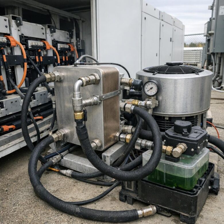
Indirect liquid cooling moves a coolant through cold plates, channels or other heat exchangers that are thermally connected to battery modules. The fluid does not normally contact the cells or energized parts directly.
Liquid has a greater ability than air to transport heat through a compact circuit. This makes liquid cooling attractive for dense containerized systems, frequent cycling, high charge or discharge rates and sites where enclosure space is limited.
| Liquid-Cooling Component | Function | Condition to Monitor |
|---|---|---|
| Cold plate or cooling channel | Transfers module heat into the coolant | Thermal contact, blockage, deformation and temperature uniformity |
| Pump | Maintains required coolant flow | Flow, pressure, vibration, power consumption and fault status |
| Heat exchanger or chiller | Rejects heat outside the battery circuit | Fouling, fan operation, refrigerant condition and ambient derating |
| Expansion tank | Accommodates fluid expansion and stabilizes the circuit | Level, pressure, leakage and gas accumulation |
| Coolant | Carries thermal energy through the loop | Concentration, contamination, electrical properties, corrosion and compatibility |
| Leak detection | Provides early warning of escaped fluid | Sensor health, alarm routing and periodic functional testing |
Liquid cooling performs best when integrated into the battery module design. Retrofitting cold plates or changing coolant without manufacturer approval can alter structural loading, electrical insulation, material compatibility, fire-test evidence and warranty coverage.
Hybrid Systems
Many high-capacity systems are effectively hybrid even when marketed as liquid cooled. A coolant loop may regulate the battery modules while an HVAC system manages the enclosure, electronics and humidity. Separate ventilation or emergency gas-management equipment may also be present.
Module Layer
Liquid cold plates, thermal interface materials, module sensors and local flow distribution manage cell-generated heat.
Enclosure Layer
HVAC, insulation, shading, humidity control and internal air circulation manage the container environment.
Site Layer
Outdoor heat rejection, spacing, solar exposure, drainage, wind, dust and ambient conditions determine final performance.
Hybrid systems can provide strong control, but the interfaces must be clear. The battery management system, thermal controller, HVAC controller and site supervisory system should not respond to the same condition with conflicting commands.
Immersion Cooling
Immersion cooling places cells or modules in direct contact with a specially selected dielectric fluid. The approach can create close thermal contact and reduce the need for conventional airflow around each component.
It is not yet a universal default for stationary storage. Fluid compatibility, sealing, swelling, electrical properties, service procedures, contamination, long-term material stability, recycling and the behavior of the complete assembly during abnormal events must be validated.
- Battery manufacturer explicitly approves the fluid
- Cell seals and plastics remain compatible over time
- Fluid properties remain stable across the service life
- Electrical insulation is verified after contamination
- Maintenance can be performed without uncontrolled exposure
- Fluid handling and disposal procedures are defined
- Fire-test evidence covers the actual configuration
- Leak containment and environmental risks are addressed
Do not assume that a dielectric fluid eliminates thermal-runaway or fire risk. The safety response depends on the cells, fluid, enclosure, spacing, ignition sources, vented gases, heat release, pressure behavior and tested system configuration.
Phase-Change Materials and Passive Thermal Support
Phase-change materials can absorb heat while changing physical state. Heat pipes, thermal spreaders and high-conductivity interface materials can also redistribute heat away from local hot spots.
These technologies may improve transient response, especially during short high-power events. They do not create an unlimited heat sink. Once the passive material has absorbed or redistributed heat, an active system still needs to reject that energy to the environment.
Passive support is most useful when its recovery period is understood. A material that performs well during one short discharge may offer little benefit during repeated events if it cannot release stored heat between cycles.
Cold-Climate Heating Is Part of Thermal Management
In cold climates, battery heating may be required before charging or high-power operation. Heating can come from reversible heat pumps, liquid-loop heaters, enclosure HVAC or manufacturer-integrated module systems.
The heating strategy should warm the battery uniformly and avoid creating condensation. A cold container that is rapidly heated may leave metal surfaces, cables or internal components below the dew point even when the air temperature has increased.
| Cold-Weather Issue | Possible Effect | Design Response |
|---|---|---|
| Battery below approved charging temperature | Reduced charge acceptance or battery damage if protection is bypassed | Preheat under manufacturer-approved limits before charging |
| Uneven module heating | Different available power and state estimates between racks | Verify heater distribution and temperature spread |
| High auxiliary heating demand | Reduced net energy and longer recharge time | Include heating energy in sizing and performance guarantees |
| Condensation after warm-up | Corrosion, insulation problems and sensor faults | Coordinate heating, ventilation, humidity and dew-point control |
How to Select the Best-Fit System
-
Confirm the battery manufacturer’s operating envelope.
Record approved cell, module and coolant temperature ranges, charge and discharge derating, alarm limits, heating requirements and warranty conditions. -
Define the real duty cycle.
Model backup operation, daily cycling, peak shaving, frequency response, renewable shifting, idle periods and simultaneous charging or discharging at different racks. -
Calculate every significant heat source.
Include cell losses, power conversion, transformers, busbars, controls, communications, lighting, fans, pumps and other equipment inside the thermal boundary. -
Map the environmental design conditions.
Review maximum and minimum ambient temperature, humidity, solar radiation, altitude, wind, dust, salt, flooding, enclosure leakage and indoor ventilation. -
Compare thermal architectures.
Evaluate air, HVAC, liquid, hybrid, passive and specialized immersion concepts using the same duty cycle and environmental assumptions. -
Analyze temperature uniformity.
Confirm expected maximum, minimum and temperature spread across cells, modules and racks rather than relying only on average enclosure temperature. -
Evaluate single failures and degraded operation.
Model fan, pump, chiller, HVAC, sensor, communication and power-supply failures together with blocked filters and reduced coolant flow. -
Coordinate safety and code compliance.
Confirm that cooling, ventilation, fire detection, emergency shutdown, spacing and test evidence refer to the actual proposed configuration. -
Review lifecycle serviceability.
Check access to filters, pumps, valves, coolant ports, sensors, coils, drains and heat exchangers before approving the layout. -
Commission against the thermal design basis.
Verify full-load performance, temperature spread, humidity, alarms, redundancy and fallback behavior under representative site conditions.
Define the Complete Thermal Load
The thermal model should use the battery’s expected heat generation across state of charge, temperature, current and age rather than one fixed percentage. Heat generation can differ between charging and discharging and may change as the battery ages.
Do not size cooling from battery energy capacity alone. Two systems with the same megawatt-hour rating can have very different heat loads because of their power rating, cell design, duty cycle, efficiency and enclosure density.
Design for the Actual Site Environment
| Site Condition | Thermal Concern | Possible Design Measure |
|---|---|---|
| Hot, sunny location | High ambient temperature and container solar gain | Appropriate derating, insulation, reflective surfaces, shading and larger heat rejection |
| Cold location | Reduced charge acceptance and high heating demand | Insulation, preheating, efficient heat pumps and protected operating reserves |
| Humid or coastal site | Condensation, salt corrosion and sensor degradation | Dew-point control, sealing, corrosion protection and suitable filtration |
| Dusty industrial site | Blocked filters, reduced airflow and fouled heat exchangers | Filter monitoring, accessible cleaning and condition-based maintenance |
| High altitude | Reduced air density and changed cooling-equipment performance | Apply manufacturer altitude derating and verify heat-exchanger capacity |
| Flood-prone area | Water exposure to cooling and electrical equipment | Elevation, drainage, barriers, leak paths and emergency isolation planning |
Redundancy and Failure Response
High-capacity storage should not depend on one unnoticed fan, pump, refrigerant circuit, temperature sensor or control power supply. The required level of redundancy depends on project criticality, available derating and the time operators have to respond.
Continue Safely
A redundant component assumes the load, temperatures remain controlled and the system creates a maintenance alarm.
Derate Operation
Charge or discharge power is reduced automatically to match the remaining heat-removal capability.
Controlled Shutdown
The battery enters a defined safe state when temperature, flow, pressure or system availability crosses an approved limit.
| Failure | Early Indicator | Expected Control Response |
|---|---|---|
| Fan failure | Loss of status, low airflow or rising rack temperature | Start redundant fan, alarm and derate if required |
| Pump failure | Low flow, pressure change, motor fault or rapid coolant-temperature rise | Transfer to standby pump or reduce battery power immediately |
| Coolant leak | Leak sensor, falling level or pressure loss | Isolate affected circuit and follow approved electrical-safety response |
| Blocked filter or heat exchanger | Higher pressure drop, fan power or approach temperature | Create maintenance warning and reduce output before limits are reached |
| Temperature-sensor fault | Fixed, implausible or inconsistent reading | Use validated fallback limits and escalate maintenance |
| Thermal-controller communication loss | Missing data or stale command | Enter a documented local fallback mode rather than uncontrolled operation |
Failure detection should not depend on one measurement. Pump status without verified coolant flow, for example, may indicate that the motor is running while a closed valve or blockage prevents effective circulation.
Monitoring and Control Signals
Trend analysis is more valuable than a dashboard showing only current values. One rack that is consistently warmer than neighboring racks may indicate restricted flow, airflow bypass, connection resistance, sensor drift or an internal battery issue.
Do not increase alarm thresholds merely to stop repeated warnings. Recurrent temperature, coolant, fan, pump or humidity alarms should trigger root-cause investigation before normal high-power operation continues.
Thermal Management and Fire Safety
Thermal management controls normal operating temperature and can support early detection of abnormal heat. It does not replace battery protection, fire detection, explosion control, spacing, emergency shutdown or tested system-level safety measures.
In jurisdictions using North American standards, stationary battery projects may be reviewed against UL 9540 system certification, UL 9540A thermal-runaway fire-propagation testing and the edition of NFPA 855 adopted by the authority having jurisdiction. International projects may use IEC 62933 and other national or regional requirements.
| Document or Standard | Primary Role | What It Does Not Prove Alone |
|---|---|---|
| UL 9540 | Safety of an integrated energy-storage system and its equipment | That every proposed site layout is automatically approved |
| UL 9540A | Test method for evaluating thermal-runaway fire propagation behavior | That the battery cannot experience thermal runaway |
| NFPA 855 | Installation requirements intended to mitigate stationary ESS hazards | That manufacturer maintenance and electrical requirements can be ignored |
| IEC 62933 series | Planning, performance, environmental and safety considerations for electrical energy storage | That all local permitting and grid requirements are identical |
Fire-test evidence should match the proposed product and installation. Changes in module spacing, enclosure design, coolant, ventilation, suppression, state of charge or rack arrangement may affect whether existing test results remain applicable.
Procurement Specifications to Request
Thermal Performance Requirements
- Maximum approved battery and power-electronics temperatures
- Maximum temperature spread across modules and racks
- Thermal performance at specified ambient extremes
- Cooling capacity at maximum continuous charge and discharge power
- Performance with expected solar heat gain and enclosure loading
- Required heating capacity for cold-weather operation
- Humidity and dew-point control strategy
- Cooling-system auxiliary power and energy consumption
- Fan, pump, HVAC or chiller redundancy requirements
- Automatic derating and shutdown sequences
- Leak detection and coolant compatibility documentation
- Sensor quantity, placement, accuracy and calibration requirements
- Alarm, event and remote-notification functionality
- Maintenance intervals, access and expected consumables
- Thermal modeling and factory or field validation results
- Safety certificates and fire-test reports for the proposed configuration
The owner should also define the measurement boundary for thermal auxiliary consumption. A system with strong cell efficiency may still have significant net losses if HVAC, chillers, heaters and pumps consume large amounts of energy.
Commissioning Tests
Acceptance Records Should Include
- Final thermal design basis
- Approved operating and alarm limits
- Temperature-sensor location map
- Coolant schematic and component list
- Airflow or hydraulic balancing results
- Full-load thermal test data
- Humidity and condensation-control results
- Redundancy and failure-response tests
- Cooling auxiliary-energy measurements
- As-built controls and communication diagrams
- Maintenance procedures and spare-parts list
- Safety certificates and applicable test reports
Maintenance Priorities
| Maintenance Area | Typical Check | Warning Pattern |
|---|---|---|
| Air filters and coils | Inspect differential pressure, dust buildup and heat-exchanger condition | Increasing fan power or enclosure temperature |
| Fans and pumps | Review runtime, vibration, current, bearings, faults and standby readiness | Frequent starts, unstable flow or abnormal noise |
| Coolant | Test level, concentration, contamination, corrosion protection and compatibility | Discoloration, debris, falling pressure or poorer heat transfer |
| Leaks and drains | Inspect fittings, hoses, condensate lines, containment and leak sensors | Moisture, unexplained fluid loss or repeated sensor events |
| Humidity control | Review dew point, seals, dehumidification and door-opening history | Condensation, corrosion or insulation alarms |
| Thermal trends | Compare rack temperatures at similar power, charge level and ambient conditions | One rack or module gradually separating from the group |
Maintenance frequency should follow manufacturer requirements and reflect the site. A clean indoor room may need less frequent filter service than a dusty outdoor installation. A liquid circuit exposed to seasonal temperature extremes may require more detailed coolant and freeze-protection checks.
Common Selection Mistakes
| Mistake | Possible Consequence | Better Approach |
|---|---|---|
| Choosing from battery capacity alone | Cooling is undersized for the actual battery power and cycling profile | Model heat generation across current, temperature and state of charge |
| Checking average temperature only | Local hot spots and uneven aging remain hidden | Track maximum, minimum and temperature spread |
| Ignoring cooling auxiliary energy | Net project efficiency and available discharge energy are overstated | Include HVAC, pumps, fans and heaters in performance models |
| Using laboratory ambient conditions | System derates in real outdoor heat, cold, humidity or dust | Use project-specific environmental design conditions |
| Assuming liquid cooling eliminates HVAC | Electronics and humidity remain uncontrolled | Evaluate the complete enclosure thermal environment |
| Ignoring condensation | Corrosion, insulation degradation and sensor problems | Control humidity and dew point during cooling and heating |
| Failing to test backup cooling | A redundant component is unavailable when the primary system fails | Functionally test redundancy during commissioning and maintenance |
| Changing coolant or setpoints informally | Material incompatibility, warranty loss or unsafe operation | Use manufacturer-approved materials and controlled engineering changes |
| Treating cooling as the fire-protection system | Propagation, gas and emergency hazards remain unaddressed | Coordinate cooling with tested fire and emergency measures |
When Professional Investigation Is Urgent
Repeated temperature alarms, frequent power derating, coolant leaks, pump faults, unexplained pressure loss, condensation, corrosion, rapid heating or growing temperature differences should be investigated promptly.
A qualified specialist should also review any proposed change to battery layout, rack spacing, coolant, airflow, HVAC settings, enclosure penetrations, fire-protection equipment or energy-storage capacity.
Follow the emergency plan immediately for smoke, venting, unusual odor, rapid abnormal heating, swelling, physical damage, water intrusion or critical battery alarms. Do not approach, open or repeatedly reset affected equipment unless the approved response procedure specifically authorizes the action.
Final Recommendation
For modern high-density lithium-ion storage, indirect liquid cooling combined with enclosure-level temperature and humidity control is often the strongest mainstream architecture. It can provide direct heat removal and better temperature uniformity while the enclosure system protects electronics and manages moisture.
Forced-air and HVAC-based designs remain valid for moderate-density systems, indoor rooms, backup applications and projects where simplicity and maintenance familiarity are priorities. Their performance depends heavily on airflow distribution, filtration and avoidance of hot-air recirculation.
Immersion cooling, phase-change materials and other advanced approaches can be valuable in specialized designs, but they should be selected only with battery-manufacturer approval, compatible materials, suitable servicing procedures and safety evidence for the complete configuration.
The final selection should be based on worst-case operating conditions, temperature uniformity, humidity control, auxiliary consumption, redundancy, service access and verified failure response. A thermal system is successful when it protects performance throughout the project life and remains understandable, testable and maintainable by the owner.
Frequently Asked Questions
What is the best cooling system for grid-scale battery storage?
There is no universal best system. Indirect liquid cooling is often well suited to dense, frequently cycled lithium-ion systems, while air cooling or enclosure HVAC may be sufficient for moderate-density and lower-duty installations. Selection should follow project-specific thermal modeling and manufacturer requirements.
Is liquid cooling always more efficient than air cooling?
Liquid can transport heat through a smaller space and may improve module temperature uniformity. Total system efficiency still depends on pump, chiller, heat-exchanger, fan and control energy, as well as the outdoor environment and operating load.
Does a liquid-cooled battery container still need HVAC?
It may. Liquid cooling can manage module heat, while HVAC or another enclosure system manages humidity, power electronics, controls, busbars and other equipment that releases heat into the container.
Can cooling stop thermal runaway?
Normal cooling may reduce thermal stress and help keep cells within approved limits, but it should not be treated as a guarantee against thermal runaway. Cell defects, electrical abuse, physical damage and other failures require additional protection, detection, testing and emergency measures.
Why does temperature uniformity matter?
Modules that repeatedly operate at different temperatures may age at different rates and reach protection limits at different times. This can reduce usable rack capacity even when the system’s average temperature appears acceptable.
Can phase-change materials replace active cooling?
Usually not for continuous high-capacity operation. They can absorb temporary heat spikes, but the stored heat must later be removed. Their recovery period should be evaluated against the actual cycling schedule.
What should be monitored in a liquid-cooling loop?
Useful signals include inlet and outlet temperature, flow, pressure, coolant level, pump status, leak detection, chiller performance and temperature spread between battery racks.
How should condensation be prevented?
The design should coordinate air temperature, surface temperature, humidity, insulation, sealing and dew point. Cooling or heating equipment should not create cold surfaces that remain below the enclosure dew point.
What is the difference between UL 9540 and UL 9540A?
UL 9540 addresses the safety of integrated energy-storage systems and equipment. UL 9540A is a test method used to evaluate thermal-runaway fire-propagation behavior at defined testing levels.
When should a thermal management specialist be contacted?
Professional review is appropriate before procurement and whenever the system shows repeated alarms, uneven temperatures, cooling failure, leaks, condensation, rapid heating, unexplained derating or proposed changes to the battery or enclosure configuration.
Official Standards and Technical Resources
- U.S. Department of Energy and Sandia National Laboratories — Energy Storage Handbook
- UL Solutions — Energy Storage System Testing and UL 9540 Certification
- UL Solutions — UL 9540A Thermal-Runaway Fire-Propagation Test Method
- NFPA 855 — Standard for the Installation of Stationary Energy Storage Systems
- IEC 62933-5-1:2024 — Safety Considerations for Grid-Integrated Energy Storage Systems
- IEC 62933-3-1:2025 — Planning and Performance Assessment of Electrical Energy Storage Systems
- IEC 62933-4-3:2025 — Environmental Conditions Affecting Battery Energy Storage Systems
- National Renewable Energy Laboratory — Lithium-Ion Battery Thermal Characterization

The Ogumex Editorial Team creates practical, research-based content about commercial solar energy, battery storage, clean technologies, and sustainable industrial solutions. Our goal is to explain complex topics clearly, helping professionals, businesses, and informed readers make better decisions. Each article is reviewed for clarity, accuracy, and usefulness using reliable industry and official sources.