
By Ogumex Editorial Team
Communication alarms in a commercial battery energy storage system can indicate anything from a loose connector to a failed controller, incompatible firmware or electrically noisy installation. The alarm itself rarely identifies the root cause.
Effective troubleshooting separates power and physical-layer faults from protocol, configuration and application-layer problems. It also preserves evidence before controllers are reset or settings are changed.
Safety warning: Battery cabinets, power conversion equipment and auxiliary circuits may remain energized at hazardous voltages when the system is stopped. Follow the manufacturer’s service instructions, lockout/tagout requirements and site electrical-safety procedures. Do not bypass interlocks, force contactors, probe energized conductors or alter protective settings unless authorized and qualified to do so.
Why a BMS Communication Alarm Is Not a Diagnosis
A commercial system may contain cell-monitoring units, rack controllers, a system-level BMS, gateways, the power conversion system, an energy management system and SCADA. A communication failure at one interface can therefore produce alarms in several other devices.
For example, a SCADA timeout does not prove that a battery rack is offline. The rack may still be communicating with the system BMS while an upstream Ethernet gateway, switch, register map or polling process has failed. Conversely, a dashboard can continue displaying stale values after communication has stopped unless data-quality and timestamp information is checked.
| Observed pattern | Initial suspects | Evidence to collect first |
|---|---|---|
| One rack or module repeatedly disappears | Local power, connector, address, branch wiring or controller | Node reboot history, supply voltage, connector condition and bus traffic at that branch |
| All devices on one serial segment fail | Master, gateway, termination, trunk cable or auxiliary supply | Gateway status, bus resistance, master requests and physical-layer waveform |
| Values differ between BMS, PCS and SCADA | Register mapping, scaling, byte order, stale data or time mismatch | Raw registers, quality flags, source timestamps and map revisions |
| Errors appear during charging, contactor operation or high PCS output | Noise, common-mode voltage, grounding, shielding or supply disturbance | Time-correlated communication counters, auxiliary voltage and operating state |
| Fault begins after maintenance or an update | Polarity, missing termination, duplicate address, changed configuration or incompatible firmware | Before-and-after configuration files, firmware versions and maintenance records |
A Structured Troubleshooting Workflow
- Place the system in an approved safe state. Determine whether the failed link carries monitoring data only or participates in protective control, contactor commands, current limits or shutdown functions.
- Preserve evidence before resetting equipment. Export alarms, event logs, switch counters, controller diagnostics and configuration files. Photograph indicators and record exact timestamps.
- Define the scope. Identify the first device reporting the fault, every affected node and whether healthy local communication continues downstream of the alarm point.
- Check power before data. Verify controller supply voltage, fuses, grounding and reboot or brownout records. Measure auxiliary voltage at the affected device under the operating condition that produces the fault, using approved test points and rated instruments.
- Compare against the approved baseline. Confirm topology, cable type, termination locations, addresses, baud rates, VLANs, IP settings, register maps and firmware compatibility.
- Change one variable at a time. Record the original value, reason for the change, result and rollback action. Avoid simultaneous firmware, addressing and wiring changes.
Diagnosing CAN Communication Faults
Inspect the topology and cable path
High-speed CAN is normally implemented as a linear trunk with termination at the two physical ends. Long stubs, star connections, additional terminators and branches added during maintenance can create reflections and reduce signal margin.
Check the complete route rather than only the connector at the alarmed device:
- Confirm CAN-H and CAN-L continuity and polarity against the manufacturer’s drawings.
- Inspect plugs, terminal blocks, crimp contacts, cable glands and cabinet pass-throughs.
- Look for corrosion, moisture, pin recession, damaged shielding and cables routed beside high-current conductors.
- Verify that replacement modules have the correct node address and supported communication profile.
- Confirm that shield and reference conductors are connected exactly as designed.
Use resistance as a screening test
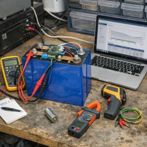
With the network powered down, discharged as required and isolated according to the manufacturer’s procedure, measure resistance between CAN-H and CAN-L. A correctly accessible network with two 120-ohm end terminations will commonly measure near 60 ohms because the resistors are in parallel.
| Indicative reading | Possible interpretation |
|---|---|
| Near 60 ohms | Two 120-ohm terminations are probably visible to the meter |
| Near 120 ohms | One termination may be missing, switched out or separated by an open circuit |
| Well below 60 ohms | Extra termination, incorrect resistor or partial short may be present |
| Very high or open | Broken pair, disconnected trunk or missing terminations may be present |
This measurement does not prove that signal integrity is acceptable. Integrated termination circuits, gateways, protection components and parallel paths can alter the result. Compare readings with the OEM schematic and a known-good segment.
Analyze protocol and waveform behavior
A CAN analyzer can reveal missing heartbeat messages, repeated retransmissions, error frames, acknowledgment problems, bus-off events and rising transmit or receive error counters. Confirm the configured bit rate, node identity and protocol revision before interpreting missing messages as hardware failure.
If the resistance and configuration are correct but faults persist, a qualified specialist may need to examine CAN-H and CAN-L with appropriately rated differential instrumentation. Ringing, distorted edges, inadequate differential amplitude or excessive common-mode movement can identify problems that protocol logs alone cannot show. Never attach a conventional oscilloscope ground clip where it could short an isolated or energized circuit.
Diagnosing RS-485 and Modbus RTU Faults
Separate RS-485 from Modbus
RS-485 defines the electrical interface; Modbus RTU is one possible protocol operating over it. A healthy RS-485 waveform can still carry requests that a device rejects because its address, serial format or register map is wrong.
Verify the physical layer
- Confirm A/B polarity from the documentation for both devices rather than relying on conductor color or informal positive/negative labels.
- Maintain the twisted pair to the terminal and avoid unnecessary untwisting.
- Use a trunk topology with short stubs unless the manufacturer specifies another arrangement.
- Check termination only at the appropriate ends of the main cable. Do not add a terminator at every device.
- Verify any fail-safe bias network. Too many bias networks can overload the bus, while missing or unsuitable biasing can produce framing errors during idle periods.
- Check the signal reference, shield and isolation arrangement against the engineered design.
As with CAN, two 120-ohm parallel terminations may produce a reading near 60 ohms on an unpowered RS-485 pair, but this is not universal. Some short or low-rate links intentionally use different termination arrangements. Follow the equipment and network design documentation.
Verify Modbus settings and responses
Check the slave address, baud rate, parity, data bits and stop bits at both ends. Then compare the BMS register-map revision with the gateway, PCS or EMS configuration.
Use an approved serial analyzer or diagnostic master to determine whether:
- The master is transmitting requests at the expected interval.
- The intended slave replies and no duplicate address responds.
- CRC failures occur on requests, responses or both.
- The device returns Modbus exception codes.
- Response time exceeds the master’s timeout.
- Polling is too aggressive for the controller or gateway.
- Register addresses, function codes, scaling, signed values, word order and byte order match the current map.
Do not write to BMS registers during diagnosis unless the manufacturer explicitly authorizes the operation. A generic Modbus tool can expose writable control points as easily as read-only measurements.
Diagnosing Ethernet and Modbus TCP Faults
Start at the link and switch port
Confirm that the BMS gateway and switch agree on link status, speed and duplex. Review managed-switch counters for link flaps, frame-check-sequence or CRC errors, discarded frames and interface resets. Increasing physical-layer errors justify inspecting or substituting the cable, connector, patch panel and switch port before replacing the BMS gateway.
Port counters are indicators rather than final diagnoses. Packet errors may originate from cabling, connector workmanship, electromagnetic interference, a marginal physical-layer transceiver or incorrect hardware configuration.
Check addressing and network segmentation
- Verify the IP address, subnet mask, default gateway and DNS settings where applicable.
- Check the address-management record and ARP information for duplicate IP addresses.
- Confirm VLAN membership, trunk/access-port configuration and permitted routes.
- Review firewall and access-control changes affecting the required protocol and port.
- Confirm that redundant links are not creating an unintended loop or unstable path.
Testing from the same subnet can help distinguish a local device problem from routing or firewall issues. Perform scans and connection tests only under the site’s operational-technology cybersecurity procedures.
Inspect packet and application behavior
When authorized, use switch port mirroring or a network tap to capture traffic without disrupting the control network. Look for unanswered connection attempts, TCP retransmissions, resets, repeated ARP resolution, excessive polling and connections that remain open after a client failure.
For Modbus TCP, verify the destination address and port, unit identifier where used, register map, transaction handling, timeout and the gateway’s supported number of simultaneous clients. A gateway can be reachable by ping while its Modbus service is stopped, saturated or rejecting requests.
Grounding, Shielding and Electrical Noise
Differential signaling improves noise immunity, but it does not make CAN or RS-485 immune to ground-potential differences, poor cable routing, incorrect shield bonding or transients from contactors, motors and power electronics.
Intermittent faults should be correlated with system operation. Determine whether counters increase during PCS switching, high charge or discharge current, contactor transitions, HVAC starts or auxiliary-power disturbances.
- Keep communication cables separated from high-current conductors according to the engineered installation requirements.
- Preserve cable twist and shield continuity through approved connectors and glands.
- Do not assume that a shield must always be bonded at one end or both ends; the correct arrangement depends on the system design, isolation strategy and grounding plan.
- Measure common-mode conditions only with suitable instruments and qualified personnel.
- Where ground-potential differences cannot be kept within the interface limits, consult the manufacturer about approved galvanic isolation rather than improvising a ground connection.
Build a Time-Correlated Evidence Set
Logs are most useful when all devices have accurate clocks. Check time synchronization and time zones before comparing events. Preserve original files rather than relying only on screenshots.
A useful diagnostic package includes:
- BMS master, rack and module event logs.
- PCS and EMS alarms from the same time window.
- CAN analyzer captures or Modbus request-and-response logs.
- Managed-switch counters and relevant packet captures.
- Auxiliary supply measurements and controller reboot records.
- Battery operating state, current, contactor state and ambient or cabinet temperature.
- Firmware versions, protocol-map revisions and configuration exports.
- A written record of every test and change.
Compare source timestamps and data-quality flags as well as displayed values. A SCADA value that differs from the local BMS may be stale, incorrectly scaled or translated from the wrong register rather than evidence of a defective sensor.
Firmware and Configuration Checks
Maintain a compatibility matrix for the system BMS, rack controllers, communication gateway, PCS, EMS and SCADA driver. Record exact firmware builds, hardware revisions, CAN profiles, Modbus maps and configuration-file versions.
After an update or controller replacement:
- Confirm that all required components are on manufacturer-approved combinations.
- Check whether node IDs, serial settings, IP parameters or register maps reverted to defaults.
- Verify that the correct configuration was loaded for the battery model and system capacity.
- Review release notes and known issues supplied by the manufacturer.
- Validate communication and protective behavior in an approved maintenance state before returning the system to service.
Do not install unapproved firmware, cross-load files from another site or downgrade controllers without a documented manufacturer procedure. Preserve backups and a tested rollback path before making changes.
Common Troubleshooting Mistakes
- Resetting before exporting logs: This can erase the sequence needed to identify the initiating fault.
- Replacing controllers before checking power and cabling: Supply interruptions and physical-layer defects frequently resemble controller failure.
- Adding termination without checking topology: Extra resistors can worsen signal integrity by loading the bus.
- Changing several settings at once: This prevents a defensible root-cause determination.
- Ignoring timestamps and quality flags: A plausible value may be old or invalid.
- Testing only while the system is idle: Noise and supply faults may appear only during switching or high-power operation.
- Treating every CRC counter as proof of a bad cable: The counter identifies corrupted traffic, not its exact physical cause.
- Using unauthorized diagnostic writes or network scans: These actions can disrupt an operational BMS or alter safety-relevant settings.
When to Stop and Escalate
Escalate to the battery manufacturer, system integrator or qualified controls specialist when:
- Cell voltage, temperature, isolation, contactor state or other safety-relevant data is unavailable or contradictory.
- Several nodes enter bus-off or repeatedly reboot.
- Communication can be restored only by bypassing an interlock or protective function.
- Waveform or common-mode measurements require access to energized hazardous circuits.
- Firmware compatibility is unclear or a signed, manufacturer-controlled package is required.
- The fault recurs after verified wiring, termination, addressing and configuration checks.
- There are signs of overheating, arcing, electrolyte release, smoke, water intrusion or enclosure damage.
If a hazardous battery condition is suspected, follow the site emergency response plan and manufacturer instructions. Do not open or re-energize the affected enclosure merely to continue communication testing.
A Disciplined Diagnosis Protects Safety and Uptime
The fastest reliable path is usually to verify safety status and controller power, preserve evidence, define the affected segment and then work upward from the physical layer to protocol and application configuration. Termination readings, packet captures and error counters are most valuable when compared with the approved topology and a known-good baseline.
Communication alarms should not be dismissed, but they should not automatically trigger expensive hardware replacement either. A documented, one-change-at-a-time process helps distinguish a damaged bus from a mapping error, overloaded gateway, incompatible update or upstream network fault.
Sources and further reading
- CAN in Automation: CAN high-speed transmission
- CAN in Automation: CAN Newsletter, June 2026
- Analog Devices: AN-960 RS-485/RS-422 Circuit Implementation Guide
- Texas Instruments: DP83869 Troubleshooting Guide
- UL Solutions: Functional Safety of Electronics and Software Used in Energy Storage Products

The Ogumex Editorial Team creates practical, research-based content about commercial solar energy, battery storage, clean technologies, and sustainable industrial solutions. Our goal is to explain complex topics clearly, helping professionals, businesses, and informed readers make better decisions. Each article is reviewed for clarity, accuracy, and usefulness using reliable industry and official sources.